

< Previous | Contents | Next >
Section 6 Steel Forgings
601. Steel forgings
1. Application
(1) The requirements in 601. are to apply to the steel forgings(except those specified in 602., 603. and 604.) intended to be used for the components of hull construction, equipments, and machi- nery specified in each Part, and where relevant, these requirements are also applicable to materi- al for forging stock and to rolled bars intended to be machined into components of simple shape (hereinafter referred to as the "steel forgings").
(2) Steel forgings having characteristics differing from those specified in 601. are to comply with the requirements in 101. 2.
2. Kinds The steel forgings are classified as specified in Table 2.1.83 and 2.1.84.
3. Manufacturing process
(1) Steel forgings are to be manufactured from the killed steel.
(2) Adequate discards are to be made from the top and bottom of each ingot to ensure freedom
from piping and harmful segregation in the finished forgings.
(3) Steel forgings are to be hot worked by press or hammer from ingots, blooms forged or rolled
from ingots or blooms made from ingots by a combination of rolling and forging.
(4) Steel forgings are to be gradually and uniformly hot worked and are to be brought as nearly as
possible to the finished shape and size. Where practicable, they are to be worked so as to
cause metal flow in the most favourable direction having regard to the mode of stressing in service.
(5) The reduction ratio is to comply with the following;
![]()
![]()
(a) For components where the fibre deformation is mainly longitudinal; the total reduction ratio is to be not less than those shown in Table 2.1.80. See Guidance
![]()
![]()
Table 2.1.80 Reduction Ratio
Method of manufacture | Description(1) | Total reduction(2)(3) |
Made directly from ingots or from forged blooms or billets | L D L D | 3 : 1 1.5 : 1 |
Made from rolled products | L D L D | 4 : 1 2 : 1 |
NOTES: (1) L and D are the length and diameter respectively of the part of the forging under consideration. (2) The reduction ratio is to be calculated with reference to the average cross-sectional area of the ingot. Where an ingot is initially upset, this reference area may be tak- en as the average cross-sectional area after this operation. (3) For rolled bars used as a substitute for forgings the reduction ratio is to be not less than 6:1. | ||
(b) Disc type forgings such as gear wheels are made by upsetting
(i) The thickness of any part of the disc is to be not more than one half of the length of the billet from which it was formed provided that this billet has received an initial forging reduction of not less than 1.5:1.
(ii) Where the piece used has been cut directly from an ingot or where the billet has re- ceived an initial reduction of less than 1.5:1, the thickness of any part of the disc is to be not more than one third of the length of the original piece.
![]()
![]()
(6) The shaping of forgings or rolled slabs and billets by flame cutting, scarfing or arc-air gouging is to be undertaken in accordance with recognized good practice and, unless otherwise approved, is to be carried out before the final heat treatment. Preheating is to be employed when neces- sitated by the composition and thickness of the steel. For certain components, subsequent ma- chining of all flame cut surfaces may be required. See Guidance
![]()
(7) When
posed
two or more forgings are joined by welding to form a composite component, the pro- welding procedure specification is to be submitted for approval to the Society. Welding
procedure qualification tests may be required.
4. Heat treatment
![]()
![]()
(1) Except as provided in (5), after completion of all hot working operations, forgings are to be supplied in one of the conditions given in Table 2.1.81. to refine the grain structure and to obtain the required mechanical properties. No annealed forging is to be removed from the fur- nace until the temperature of the entire furnace charge has fallen to or below a temperature of 455°C. The tempering temperature is to be not less than 550 . See Guidance
Table 2.1.81 Heat Treatment
Kind | Heat treatment |
Carbon steels | Annealed Normalized Normalized and tempered Quenched and tempered |
Alloy steels | Quenched and tempered |
(2) Alternatively, alloy steel forgings may be supplied in the normalized and tempered condition, in which case the specified mechanical properties are to be agreed with the Society.
(3) Steel forgings which are subjected to any hot work after heat treatment, are to be heat treated
again.
(4) If a forging is locally reheated or any straightening operation is performed after the final heat
treatment, consideration is to be given to a subsequent stress relieving heat treatment.
(5) Where induction hardening or nitriding is to be carried out, forgings are to be heat treated at an appropriate stage to a condition suitable for this subsequent surface hardening.
(6) Where carburizing is to be carried out, forgings are to be heat treated at an appropriate stage
(generally either by full annealing or by normalizing and tempering) to a condition suitable for subsequent machining and carburizing.
(7) Where it is intended to surface harden forgings, full details of the proposed procedure and spec- ification are to be submitted for the approval of the Society. For the purposes of this approval, the manufacture may be required to demonstrate by test that the proposed procedure gives a
![]()
![]()
uniform surface layer of the required hardness and depth and that it does not impair the sound- ness and properties of the steel. See Guidance
(8) Heat treatment is to be carried out in properly constructed furnaces which are efficiently main-
tained and have adequate means for control and recording of temperature. The furnace di- mensions are to be such as to allow the whole furnace charge to be uniformly heated to the necessary temperature. In the case of very large forgings alternative methods of heat treatment
will be specially considered by the Society.
Sufficient thermocouples are to be connected to the furnace charge to measure and record that its temperature is adequately uniform unless the temperature uniformity of the furnace is verified
at regular intervals.
(9) The forge is to maintain records of heat treatment identifying the furnace used, furnace charge, date, temperature and time at temperature. The records are to be presented to the surveyor on
request.
5. Chemical composition
(1) The chemical composition of steel forgings is to comply with the requirements given in Table 2.1.82.
(2) The chemical composition of each heat is to be determined by the manufacturer on a sample
taken preferably during the pouring of the heat. When multi heats are tapped into a common ladle, the ladle analysis shall apply.
(3) At the option of the manufacturer, suitable grain refining elements such as aluminium, niobium
or vanadium may be added.
analysis.
The content of such elements is to be reported in the ladle
![]()
Table 2.1.82 Chemical Composition
Steel type | Chemical composition (%) | ||||||||||
C | Si | Mn | P | S | Cr | Mo | Ni | Cu(3) | Total residual | ||
Hull and General purpose steel forging(5) | Carbon steel | 0.23(1)(2) max. | 0.45 max. | 0.30- 1.50 | 0.035 max. | 0.035 max. | 0.30(3) max. | 0.15(3) max. | 0.40(3) max. | 0.30 max. | 0.85 max. |
Low alloy steel | (4) | 0.45 max. | (4) | 0.035 max. | 0.035 max. | (4) | (4) | (4) | 0.30 max. | - | |
Machinery steel forging | Carbon steel | 0.65(1) max. | 0.45 max. | 0.30- 1.50 | 0.035 max. | 0.035 max. | 0.30(3) max. | 0.15(3) max. | 0.40(3) max. | 0.30 max. | 0.85 max. |
Low alloy steel(6) | 0.45 max. | 0.45 max. | 0.30- 1.00 | 0.035 max. | 0.035 max. | 0.40(7) min. | 0.15(7) min. | 0.40(7) min. | 0.30 max. | - | |
NOTES : (1) The carbon content of carbon steel forgings intended for welded construction is to be 0.23 % maximum. The carbon content may be increased above this level provided that the carbon equivalent (Ceq) is not more than 0.41 %. (2) The carbon content of carbon steel forgings not intended for welded construction may be 0.65 % maximum. (3) Elements are considered as residual elements. (4) Specification is to be submitted for approval. (5) Rudder stocks and pintles should be of weldable quality. (6) Where alloy steel forgings are intended for welded constructions, the proposed chemical composition is subject to approval by the Society. (7) One or more of the elements is to comply with the minimum content. | |||||||||||
6. Mechanical properties
(1) The mechanical properties of
2.1.83. and 2.1.84.
steel forgings are to comply with the requirements given in Table
(2) At the discretion of this Societies hardness tests may be required on the following: The results
of hardness tests are to be reported and, for information purposes, typical Brinell hardness val- ues are given in Table 2.1.84.
(i) Gear forgings after completion of heat treatment and prior to machining the gear teeth. The
hardness is to be determined at four positions equally spaced around the circumference of the surface where teeth will subsequently be cut. Where the finished diameter of the toothed portion exceeds 2.5 m, the above number of test positions is to be increased to eight. Where the width of a gear wheel rim forging exceeds 1.25 m, the hardness is to be determined at eight positions at each end of the forging.
(ii) Small crankshaft and gear forgings which have been batch tested.
In such cases at least one hardness test is to be carried out on each forging.
(3) Hardness tests may also be required on forgings which have been induction hardened, nitrided or carburized. For gear forgings these tests are to be carried out on the teeth after, where appli-
cable, they have been ground to the finished profile. The results of such tests are to comply with the approved specifications.
7. Selection of test specimens
(1) Except as provided in (10) and (11), the test specimens for steel forgings are, after final heat treatment, to be taken lengthwise from prolongations or through bolt holes having a sectional area not less than that of the body of forging. Where batch testing is permitted according to (10), the test material may alternatively be a production part or separately forged. Separately forged test material is to have a reduction ratio similar to that used for the forgings represented.
![]()
(2) "One set of test specimens" is to consist of one tensile test specimen and when required, three charpy- V notch impact test specimen.
![]()
![]()
![]()
![]()
![]()
![]()
![]()
![]()
![]()
![]()
![]()
Specified minimum tensile strength (N m m ) | Range of upper limit(N mm ) |
< 600 | 120 |
600 | 150 |
Table 2.1.83 Kinds and Mechanical Properties for Hull Steel Forgings
Steel type | grades | Tensile test | |||||
Tensile strength (N mm ) | Yield strength (N mm ) | Elongation(%) ( (minimum) | Reduction of area(%) (minimum) | ||||
L | T | L | T | ||||
Carbon steel forgings | RSF 400H | 400 min. | 200 min. | 26 | 19 | 50 | 35 |
RSF 440H | 440 min. | 220 min. | 24 | 18 | 50 | 35 | |
RSF 480H | 480 min. | 240 min. | 22 | 16 | 45 | 30 | |
RSF 520H | 520 min. | 260 min. | 21 | 15 | 45 | 30 | |
RSF 560H | 560 min. | 280 min. | 20 | 14 | 40 | 27 | |
RSF 600H | 600 min. | 300 min. | 18 | 13 | 40 | 27 | |
Low alloy steel forgings | RSF 550AH | 550 min. | 350 min. | 20 | 14 | 50 | 35 |
RSF 600AH | 600 min. | 400 min. | 18 | 13 | 50 | 35 | |
RSF 650AH | 650 min. | 450 min. | 17 | 12 | 50 | 35 | |
Notes ; (1) Where it is proposed to use a steel with a specified minimum tensile strength intermediate to those given, corresponding minimum values for the other properties may be obtained by interpolation and the value at the first decimal place is to be subjected to the method of counting fractions over 1/2 as one and dis- regarding the rest. (2) For the upper limit of tensile strength, the following ranges for tensile strength may be additionally speci- fied:
(3) In the case of large forgings requiring two tension tests, the range of tensile strength is not to exceed 70 N mm (4) L (or T) denotes that the longitudinal axis of the test specimen is arranged parallel (or tangential) to the direction of forging. (5) For rudder stocks intended for ships with ice class notation except the lowest one(Grade ID), Charpy V-notch impact testing is to be carried out for all steel types at -10 and the average energy value is to be minimum 27 J (longitudinal test). | |||||||
![]()
![]()
![]()
![]()
![]()
![]()
![]()
![]()
![]()
![]()
![]()
![]()
Specified minimum tensile strength (N mm ) | Range of upper limit (N m m ) |
< 900 | 150 |
900 | 200 |
Table 2.1.84 Kinds and mechanical properties for machinery steel forgings
Steel type | Grades | Tensile test | Hardness test | |||||
Tensile strength (N mm ) | Yield strength (N m m ) | Elongation( ) ( ) (minimum) | Reduction of area( ) (minimum) | Hardness (HB) | ||||
L | T | L | T | |||||
Carbon steel forgings | RSF 400M | 400 min. | 200 min. | 26 | 19 | 50 | 35 | 110 - 150 |
RSF 440M | 440 min. | 220 min. | 24 | 18 | 50 | 35 | 125 - 160 | |
RSF 480M | 480 min. | 240 min. | 22 | 16 | 45 | 30 | 135 - 175 | |
RSF 520M | 520 min. | 260 min. | 21 | 15 | 45 | 30 | 150 - 185 | |
RSF 560M | 560 min. | 280 min. | 20 | 14 | 40 | 27 | 160 - 200 | |
RSF 600M | 600 min. | 300 min. | 18 | 13 | 40 | 27 | 175 - 215 | |
RSF 640M | 640 min. | 320 min. | 17 | 12 | 35 | 27 | 185 - 230 | |
RSF 680M | 680 min. | 340 min. | 16 | 12 | 35 | 24 | 200 - 240 | |
RSF 720M | 720 min. | 360 min. | 15 | 11 | 35 | 24 | 210 - 250 | |
RSF 760M | 760 min. | 380 min. | 14 | 10 | 35 | 24 | 225 - 265 | |
Low alloy steel forgings | RSF 600AM | 600 min. | 360 min. | 18 | 14 | 50 | 35 | 175 - 215 |
RSF 700AM | 700 min. | 420 min. | 16 | 12 | 45 | 30 | 205 - 245 | |
RSF 800AM | 800 min. | 480 min. | 14 | 10 | 40 | 27 | 235 - 275 | |
RSF 900AM | 900 min. | 630 min. | 13 | 9 | 40 | 27 | 260 - 320 | |
RSF 1000AM | 1000 min. | 700 min. | 12 | 8 | 35 | 24 | 290 - 365 | |
RSF 1100AM | 1100 min. | 770 min. | 11 | 7 | 35 | 24 | 320 - 385 | |
NOTES : (1) Where it is proposed to use a steel with a specified minimum tensile strength intermediate to those giv- en, corresponding minimum values for the other properties may be obtained by interpolation and the val- ue at the first decimal place is to be subjected to the method of counting fractions over 1/2 as one and disregarding the rest. (2) For the upper limit of tensile strength, the following ranges for tensile strength may be additionally specified:
(3) L (or T) denotes that the longitudinal axis of the test specimen is arranged parallel (or tangential) to the direction of forging. (4) For propeller shafts intended for ships with ice class notation except the lowest one(Grade ID), Charpy V- notch impact testing is to be carried out for all steel types at -10 and the average energy value is to be minimum 27 J (longitudinal test). One individual value may be less than the required average val- ue provided that it is not less than 70 % of this average value. and, The impact test for important components for machinery is to be in accordance with the Guidance relating to the Rules specified by the Society. See Guidance (5) The hardness values are typical and are given for information purposes only. | ||||||||
![]()
(3) Test specimens are normally to be cut with their axes either mainly parallel (longitudinal test) or mainly tangential (tangential test) to the principal axial direction of each product.
(4) Unless otherwise agreed, the longitudinal axis of test specimens is to be positioned as follows.
However the axis of transverse specimens may be located close to the surface of the forgings
(a) for thickness or diameter up to maximum 50 mm, the axis of test specimens is to be at the mid-thickness or the center of the cross section.
(b) for thickness or diameter greater than 50 mm, the axis is to be at one quarter thickness (mid-radius) or 80 mm, whichever is less, below any heat treated surface.
(5) Except as provided in (10), the number and direction of tests is to be as given in (a) through
(h) of the following requirements:
(a) Hull components such as rudder stocks, pintles etc. General machinery components such as
shafting, connecting rods, etc. : One set of tests is to be taken from the end of each forg- ing in a longitudinal direction except that, at the discretion of the manufacture, the alter- native directions or positions as shown in Fig 2.1.17., Fig 2.1.18. and Fig 2.1.19 may be
used. Where a forging exceeds both 4 tonnes in mass
and 3 m in length, one set of tests is
to be taken from each
end.
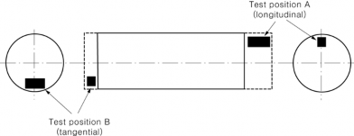
Fig 2.1.17 Plain shaft
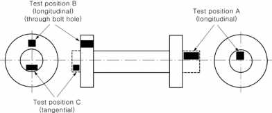
Fig 2.1.18 Flanged shaft
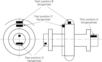
![]()
Fig 2.1.19 Flanged shaft with collar
![]()
(b) Pinions : Where the finished machined diameter of the toothed portion exceeds 200 mm one set of tests is to be taken from each forging in a tangential direction adjacent to the tooth- ed portion (test position B in Fig 2.1.20) Where the dimensions preclude the preparation of tests from this position, tests in a tangential direction are to be taken from the end of the journal (test position C in Fig 2.1.20). If however, the journal diameter is 200 mm or less the tests are to be taken in a longitudinal direction (test position A in Fig 2.1.20). Where the finished length of the toothed portion exceed 1.25 m, one set of tests is to be taken from each end.
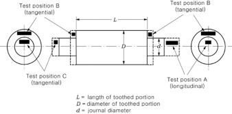
Fig 2.1.20 Pinion
(c) Small pinions : Where the finished diameter of the toothed portion is 200 mm or less one set of tests is to be taken in a longitudinal direction (test position A in Fig 2.1.20).
(d)
Gear wheels : One set of tests is to be taken from each forging in a tangential direction
(test position A or B in Fig 2.1.21).
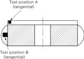
Fig 2.1.21 Gear wheel
(e) Rims intended for reduction gears and for cam shaft driving gears of diesel engine (see Pt 5, Ch 2 201.1) are to comply with the following requirements.
(i) Where the finished diameter exceeds 2.5 m or the mass (as heat treated excluding test material) exceeds 3 tonnes, two sets of tests are to be taken from diametrically opposite positions (test positions A and B in Fig 2.1.22). The mechanical properties for longi-
tudinal test are to be applied.
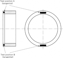
Fig 2.1.22 Gear rim (made by expanding)
![]()
(ii) Where the weight and finished diameter are different from those given in (a), one set of test specimens may be taken from one end of the rim.
(f) Pinion sleeves : One set of tests is to be taken from each forging in a tangential direction
(test position A or B in Fig 2.1.23). Where the finished length exceeds 1.25 m one set of tests is to be taken from each end.
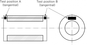
Fig 2.1.23 Pinion sleeve
(g) Crankwebs : One set of tests is to be taken from each forging in a tangential direction.
(h) Solid open die forged crankshafts : One set of tests is to be taken in a longitudinal direc- tion from the driving shaft end of each forging (test position A in Fig 2.1.24). Where the mass (as heat treated but excluding test material) exceeds 3 tonnes tests in a longitudinal direction are to be taken from each end (test positions A and B in Fig 2.1.24). Where, however, the crankthrows are formed by machining or flame cutting, the second set of tests is to be taken in a tangential direction from material removed from the crankthrow at the end opposite the driving shaft end (test position C in Fig 2.1.24).
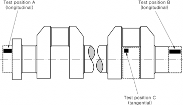
Fig 2.1.24 Solid forged crankshaft
(6) For closed die crankshaft forgings and crankshaft forgings where the method of manufacture has been approved by the Society, the number and position of test specimens is to be agreed with the Society having regard to the method of manufacture employed.
(7) When a forging is subsequently divided into a number of components, all of which are heat treated together in the same furnace charge, for test purposes this may be regarded as one forg- ing and the number of tests required is to be related to the total length and mass of the origi- nal multiple forging.
(8) The test specimens are not to be separated from the body before the final heat treatment has
been completed. In the case of stamp forging or other case of forging requiring the surface hardening process, the test specimens may be prepared at a proper stage before the final heat treatment providing that such is approved by the Surveyor.
(9) When forgings are to be carburized, sufficient test material is to be provided for both prelimi- nary tests at the forge and for final tests after completion of carburizing. For this purpose du-
plicate sets of test material are to be taken from positions as detailed in (5) except that irre-
spective of the dimensions or mass of the forging, and, in the case of forgings with integral journals,
tests are required are to be cut in
from one position only a longitudinal direction.
![]()
This test material is to be machined to a diameter of D/4 or 60 mm, whichever is less, D is the finished diameter of the toothed portion. For preliminary tests at the forge one test material is to be given a blank carburizing and heat treatment cycle simulating that
where set of which
subsequently will be applied to the forging. For final acceptance tests, the second set of test material is to be blank carburized and heat treated along with the forgings which they represent.
At the discretion of the forgemaster or gear manufacture test samples of larger cross section may be either carburized or blank carburized, but these are to be machined to the required di- ameter prior to the final quenching and tempering heat treatment. Alternative procedures for test- ing of forgings which are to be carburized may be specially agreed with the Society.
(10) Normalized forgings with mass up to 1000 kg each and quenched and tempered forgings with mass up to 500 kg each may be batch tested. A batch is to consist of forgings of similar shape
and dimensions, made from the same heat of steel, heat treated in the same furnace charge and with a total mass not exceeding 6 tonnes for normalized forgings and 3 tonnes for quenched and tempered forgings, respectively.
(11) A batch testing procedure may also be used for hot rolled bars. A batch is to consist of ei- ther:
(i) material from the same rolled ingot or bloom provided that where this is cut into individual lengths, these are all heat treated in the same furnace charge, or
(ii) bars of the same diameter and heat, heat treated in the same furnace charge and with a to-
tal mass not exceeding 2.5 tonnes.
![]()
8. Surface inspection See Guidance![]()
(1) When heat treatment and final machining are completed and, if necessary, at a proper time dur- ing machining, surface inspection is to be carried out. Where applicable, this is to include the examination of internal surfaces and bores. Testing methods and acceptance criteria are to be in accordance with the Guidance relating to the Rules specified by the Society.
(2) Dimension inspection of the steel forgings is to be conducted under the responsibility of the manufacturer, unless otherwise specified.
9. Quality
(1) Steel forgings are to be free from surface or internal defects which would be prejudicial to their proper application in service.
(2) When required by the conditions of approval for surface hardened forgings referred in 4 (7), ad-
ditional test samples are to be processed at the same time as the forgings which they represent. These test samples are subsequently to be sectioned in order to determine the hardness, shape
and depth of the locally hardened zone and which are to comply with the requirements of the approved specification.
(3) In the event of any forging proving defective during subsequent machining or testing, it is to
be rejected notwithstanding any previous certification.
10. Non-destructive inspection
![]()
![]()
(1) The following steel forgings are to be subjected to ultrasonic test at an appropriate stage of the manufacturing process and the test reports are to be showed or submitted to the Surveyor. Testing methods and acceptance criteria are to be in accordance with the Guidance relating to the Rules specified by the Society. See Guidance
(a) Rudder stock and pintle.
(b) Steel forgings given in Pt 5, Ch 2, 201.1.
(c) Thrust shafts, intermediate shafts and propeller shafts.
(d) Reduction gears and reduction gear shafts.
(e) Turbine rotors, turbine discs and turbine blades.
(2) The important parts of the following steel forgings are to be subjected to magnetic particle or liquid penetrant test at an appropriate stage of the manufacturing process. Testing methods and
acceptance criteria are to be in accordance with the Guidance relating to the Rules specified by
![]()
![]()
the Society. See Guidance
(a)
(b)
(c)
(d)
Steel forgings given in Pt 5, Ch 2, 201.1.
Propeller shafts. Reduction gears.
Turbine rotors, turbine discs and turbine blades.
(3) The Society may require sulphur print test for the portion of gear teeth.
![]()
(4) In place of the test methods given above, the Society may non-destructive inspections considered adequate by the Society.
![]()
(5) The Society may require non-destructive inspection or the steel and (2) when such is deemed necessary by the Society. See
accept the application of other
![]()
![]()
See Guidance
other than those specified in (1)
![]()
Guidance
![]()
![]()
(6) The welded parts of steel forgings used for welded construction are to be subjected to the non-destructive inspections considered adequate by the Society. See Guidance
11. Repair of defects
(1) Defects may be removed by grinding or chipping and grinding provided the component di- mensions are acceptable.
(2) After removing the defects, adequate non-destructive inspections are to be carried out to ensure that all defects have been completely removed.
(3) The resulting grooves are to have a bottom radius of approximately three times the groove
depth and are to be blended into the surrounding surface so as to avoid any sharp contours. Where the forgings from which defects where removed are used in that condition, the forgings are to be approved by the Surveyor.
(4) Repair welding of forgings except crankshaft forgings may be permitted subject to prior appro-
![]()
![]()
val of the Society. In such cases, full details of the extent and location of the repair, posed welding procedure, heat treatment and subsequent inspection procedures are to mitted for the approval. See Guidance
(5) The manufacturer is to maintain full records detailing the extent and location of repairs
the pro-
be sub-
made to
each forging and details of weld procedures and heat treatments applied for repairs. These re- cords are to be available to the Surveyor and copies provided on request.
12. Retest procedures
(1) Where the tensile test or hardness test fails to meet the requirements, additional test may be carried out in accordance with the requirements of 109.
(2) Regarding the impact tests, additional tests are to be carried out according to the requirements given in 301. 10 (3).
(3) The additional tests are to be taken, preferably from material adjacent to the original tests, but alternatively from another test position or sample representative of the forging or batch of
forgings.
(4) At the option of the manufacturer, when a forging or a batch of forgings has failed to meet the test requirements, it may be reheat treated and re-submitted for acceptance tests.
13. Marking
(1) Steel forgings which have satisfactorily complied with the required tests are to be marked with the identification mark in accordance with the requirements in 110.
(2) For steel forgings to which the requirements given in note 1. of the Table 2.1.83 and Table
2.1.84 applied, the material symbols are specified as R SF - (or R SF - A ) and the specified ten- sile strength is to be filled in symbol " - ". (e.g. For Hull and General purpose steel forging
![]()
![]()
which the specified tensile strength is 420 N m m : R SF 420H)
(3) Where carbon steel forgings are intended for welded construction specified in Note (1) of Table
2.1.82, "W" is to be suffixed to the marking. (e.g. RSF 440H-W, RSF 440M-W)
(4) The grade of Steel bars is to be indicated by suffixing a letter "B" to the symbol "R SF ". (e.g.
![]()
![]()
For Machinery steel forging which the specified tensile strength is 440 N mm : R SF B 440M)
14. Additional requirements for crank shafts
![]()
![]()
(1) Where solid crank shafts of 250 mm and over in finished diameter are manufactured by free forging, the heat treatment is normally to be carried out after crank parts are machined as near- ly as possible to the finished shape. See Guidance
![]()
![]()
(2) Where solid crank shafts, semibuilt-up crank throws and full built up crank arms are manufac- tured by special manufacturing processes, the preliminary tests instructed by the Society are to be carried out, in connection with the manufacturing processes and the selection of test specimens. See Guidance
(3) Where special manufacturing processes are adopted to reduce the size of crank shaft (refer to the requirements in Pt 5, Ch, 208. the preliminary tests instructed by the Society are to be carried out.
15. Additional requirements for turbine rotors
(1) The test specimens for turbine rotors are to be taken in accordance with the following require- ments:
![]()
(a) Where the turbine rotor is greater than 3 tons in weight, one set of longitudinal test speci- mens is to be taken from each end of the shaft portion and one set of transverse test speci- mens from the body portion respectively. (See Fig 2.1.25)
(b) Where the turbine rotor is not exceeding 3 tons in weight, one set of longitudinal test specimens is to be taken from one end of the shaft portion and one set of transverse test
specimens from the body portion respectively.
(2) For each turbine disc, one set of transverse test specimens is to be taken from the boss portion. (See Fig 2.1.26)

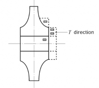
Fig 2.1.25 Selection of test specimen for turbine rotor
Note: One set of test specimens may be taken from one location given in the Figure.
Fig 2.1.26 Selection of test specimen for turbine disc
![]()
(3) Solid forged turbine rotors intended for main propulsion service where the inlet steam temper- ature exceeds 400 are to be subjected to stability tests at least once at a suitable time after rough machining or heat treatment. This requirement is also applicable to rotors fabricated by welding. The method of stability test is to be approved by the Society prior to the test.
16. Additional requirements for turbine blades Turbine blades are to be tested in accordance with the approved test specification.
602. Stainless steel forgings
1. Application
(1) Tinhge sryesqtuemiresmuesnetds
![]()
ate lotow atpepmlypetroatuthree (s-t1a6in5less asntedelovfoergiingsdefsoigr nvatlevmespearantdurep)ipeserfvititciengosr incoprriop-
sion-resisting service (hereinafter referred to as "steel forgings").
(2) Steel forgings having characteristics differing from those specified in 602. are to comply with the requirements in 101. 2.
2. Kinds Steel forgings are classified as specified in Table 2.1.85.
3. Heat treatment
Steel forgings are generally to
4. Chemical composition
The chemical composition of
2.1.85.
receive a solid solution treatment.
steel forgings is to comply with the requirements given in Table
![]()
Table 2.1.85 Grade and Chemical Composition
Grade | Chemical composition (%) | |||||||
C | Si | M n | P | S | C r | N i | Others | |
RSSF 304 | 0.08 max. | 1.00 max. | 2.00 max. | 0.040 max. | 0.030 max. | 18.00~20.00 | 8.00~12.00 | - |
RSSF 304L | 0.030 max. | |||||||
RSSF 309S | 0.08 max. | 22.00~24.00 | 12.00~15.00 | |||||
RSSF 310S | 24.00~26.00 | 19.00~22.00 | ||||||
RSSF 316 | 16.00~18.00 | 10.00~14.00 | Mo 2.00~3.00 | |||||
RSSF 316L | 0.030 max. | Mo 2.00~3.00 | ||||||
RSSF 317 | 0.08 max. | 18.00~20.00 | 10.00~15.00 | Mo 3.00~4.00 | ||||
RSSF 321 | 17.00~19.00 | 9.00~12.00 | Ti 5×C | |||||
RSSF 347 | 9.00~13.00 | Nb+Ta 10×C | ||||||
![]()
5. Mechanical properties
(1) The mechanical properties of steel forgings are to comply with the requirements given in Table 2.1.86.
(2) Where deemed necessary by the Society, impact test or corrosion resistance test may be re- quired in addition to the specified tests.
![]()
![]()
![]()
![]()
![]()
![]()
Table 2.1.86 Mechanical Properties
Grade | Tensile test | |||
Yield strength (N mm ) | Tensile strength (N mm ) | Elongation( ) ( ) | Reduction of area ( ) | |
RSSF 304L, RSSF 316L | 175 min. | 450 min. | 37 min. | 50 min. |
Other forgings | 205 min. | 520 min. | 37 min. | 50 min. |
6. Selection of the specimens
(1) The number of tensile test specimens is to be in accordance with the requirements in 601. 7.
(2) Tensile test specimens are to be taken with their longitudinal axes parallel to the direction of forging, unless otherwise specially provided by the Society.
(3) Where tests are made in accordance with the requirements in 601. 7 (5), (c) and (d), the
Surveyor may require hardness test for each forging.
7. Marking
Steel forgings which have satisfactorily complied with the required test are to be marked with the identification mark in accordance with the requirements in 110.
603. Steel forgings for chains
1. Application
(1) These requirements are to apply to the steel forgings used for anchor chain cables and accesso- ries specified in Pt 4, Ch 8 (hereinafter referred to as "steel forgings").
![]()
![]()
(2) Steel forgings for manufacture of offshore mooring chain accessories are to be in accordance with the Guidance relating to the Rules specified by the Society. See Guidance
(3) Steel forgings having characteristics differing from those specified in (1) are to comply with requirements in 101. 2.
the
![]()
![]()
(4) In addition to the requirements given in Society. See Guidance
603., general requirements may be considered by the
![]()
2. Kinds
The steel forgings are classified as specified in Table 2.1.87.
Table 2.1.87 Grades of Steel Forgings
Grade | Application | |
Steel forging for Grade 2 chain | RSFC 50 | Grade 2 chain |
Steel forging for Grade 3 chain | RSFC 70 | Grade 3 chain |
3. Heat treatment
The steel forgings are to be normalized, normalized and tempered, quenched and tempered or heat treated by the process approved by the Society.
4. Deoxidation practice and chemical composition
The deoxidation practice and chemical composition of each grade are to comply with the require-
ments given in Table 2.1.88. Elements other than specified in ject to a special approval by the Society.
Table 2.1.88 may be added sub-
Table 2.1.88 Deoxidation Practice and Chemical Composition (%)
Grade | Deoxidation | C | Si | M n | P | S | A l(1) |
RSFC 50 | Fine-grained killed | 0.24 max. | 0.15~0.55 | 1.60 max. | 0.035 max. | 0.035 max. | 0.020 min. |
RSFC 70 | 0.36 max. | 0.15~0.55 | 1.00~1.90 | 0.035 max. | 0.035 max. | 1.20 min. | |
NOTE: (1) A l content is to be represented by the total A l content and may be replaced partly by other fine grain- ing elements. | |||||||
5. Mechanical properties
The mechanical properties of each grade are to comply with
2.1.89.
the requirements given in Table
![]()
![]()
![]()
![]()
![]()
![]()
Table 2.1.89 Mechanical Properties
Grade | Tensile test | Impact test (1) | ||||
Yield strength (N m m ) (2) | Tensile strength (N m m )(2) | Elongation (%) ( ) | Reduction of area (%) | Test temp. ( ) | Average abs-orbed energy(J) | |
RSFC 50 | 295 min. | 490~690 | 22 min. | - | - | - |
RSFC 70 | 410 min. | 690 min. | 17 min. | 40 min. | 0 | 60 min. |
NOTE: (1) When the absorbed energy of two or more test specimens among a set of test specimens is less in val- ue than the specified average absorbed energy or when the absorbed energy of a single test specimen is less in value than 70 % of the specified average absorbed energy, the test is considered to have failed. | ||||||
6. Selection of test specimens
(1) One test sample is to be selected from each lot of every 25 steel forgings or fraction thereof,
which belong to the same heat. In case of steel
![]()
test samples may be reduced subject to approval
forgings having small diameter, the number of
of the Society. Where specially approved by
![]()
the Society,
the test sample may be taken from the representative part of the steel forging at a
proper time during manufacturing, or a separate sample forged to the forge ratio equivalent to
that of the
steel forgings. In this case, the test sample is to be heat treated simultaneously
with the steel forgings.
(2) For Grade 1 and Grade 2 chain bars, one tensile test specimen is to be taken from the test sample; for Grade 3 chain bars, one tensile test specimen and one set (3 pieces) of impact test specimens are to be taken from the test sample.
(3) The tensile and impact test specimens are to be taken from the test sample in the direction of forging at a depth of 1/6 diameter from the surface or as close as possible to this position. (see Fig 2.1.5)
7. Surface inspection
Surface inspection for all grades is to be carried out and it is to be confirmed that there are no harmful defects.
8. Retest procedure
Where the tensile test or impact test on the selected first test specimens fails to meet the require- ments, additional tests may be carried out according to the requirements given in 306. 9.
9. Marking
Steel forgings which have satisfactorily complied with the required tests are to be marked with the identification mark in accordance with the requirement in 110.
604. Steel forgings for low temperature service
1. Application
(1) Ttehmes reinqtueinredmedentos abree utosedappalty thtoe
![]()
tdheesigstneeltemfopregriantgusrefolrowvearlvethsanand0 pipien filtitqinugefsieidn gpaispincgarrsiyesrs-
(hereinafter referred to as "steel forgings").
(2) Steel forgings other than those specified in 604. are to comply with the requirements given in
101. 2.
Kinds The steel forgings are classified as given in Table 2.1.90. 2.
Heat treatment 3.
The steel forgings are to be normalized, normalized and tempered, quenched and tempered or dou- ble normalized and tempered.
Deoxidation practice and chemical composition 4.
The deoxidation practice and chemical composition of each grade ments given in Table 2.1.90.
are to comply with the require-
Table 2.1.90 Grades and Chemical Composition
Grade | Deoxidation | Chemical composition (%) | ||||||||
C | Si | Mn | P | S | Ni | Cr | Cu | Al | ||
RLFA | Fully killed fine grain | 0.23 max. | 0.15~0.35 | 1.10 max. | 0.030 max. | 0.030 max. | - | - | - | - |
RLFB | 0.20 max. | 0.15~0.35 | 1.60 max. | |||||||
RLFC | 0.12 max. | 0.10~0.35 | 0.55~1.00 | 0.50~0.95 | 0.50~0.95 | 0.40~0.75 | 0.04~0.30 | |||
RLF 3 | 0.20 max. | 0.15~0.35 | 0.90 max. | 3.25~3.75 | - | - | - | |||
RLF 9 | 0.10 max. | 0.10~0.35 | 0.90 max. | 8.50~9.60 | ||||||
5. Mechanical properties
(1) The mechanical properties of steel forgings are to comply with
![]()
2.1.91.
the requirements given in Table
![]()
(2) Where deemed necessary by the specified in (1).
Society, other tests may be required in addition to the tests
![]()
![]()
![]()
![]()
![]()
![]()
![]()
![]()
Table 2.1.91 Mechanical Properties
Grade | Tensile test | Impact test (2) | ||||
Yield strength (N mm ) | Tensile strength (N mm ) | Elongation (%) ( | Reduction of area (%) | Test temp. ( ) | Average absorbed energy (J) | |
RLFA | 205 min. | 410 min. | 23 min. | 40 min. | 40(1) | 27 min. |
RLFB | 275 min. | 490 min. | 20 min. | 50(1) | ||
RLFC | 205 min. | 410 min. | 23 min. | 60(1) | ||
RLF 3 | 275 min. | 490 min. | 23 min. | 50 min. | 95 | 34 min. |
RLF 9 | 520 min. | 680 min. | 19 min. | 45 min. | 196 | 41 min. |
NOTES: (1) Impact test temperature for steel forgings specified in Pt 7, Ch 5 is to be 5 below the design temperature or -20 , Whichever is the lower. (2) When the absorbed energy of two or more test specimens among a set of test specimens is less in value than the specified average absorbed energy or when the absorbed energy of a single test specimen is less in value than 70 % of the specified average absorbed energy, the test is consid- ered to have failed. | ||||||
![]()
![]()
6. Selection of tests specimens
(1) The number of test specimens is to be in accordance with the requirements specified in 601. 7.
(2) The test specimens for tensile and impact tests are to be cut with their longitudinal axes paral- lel to the direction of forging except where otherwise specially specified.
(3) Where tests are made in accordance with the requirements in 601. 7 (5), (c) and (d), the Surveyor may require a hardness test for each forging.
7. Retest procedures
(1) Where the tensile tests fail to meet the requirements, additional tests may be carried out accord- ing to the requirements given in 109.
(2) Regarding the impact tests, additional tests are to be carried out according to the requirements given in 304. 9.
8. Marking
Marking for steel castings is to comply with the requirements given in 601. 13. (1) and in case the requirement in Note (1) of Table 2.1.91. has been applied, "impact test temperature T" is to be suffixed to the marking (e.g. R L F A - 25T )
![]()